


Shopping Cart
There are no more items in your cart
The crossover is a device that is integrated into all speakers, regardless of the brand. But what is it and what is it for? Discover all the information below.
Speakers with more than one transducer require an electronic circuit that divides the musical signal to each of the transducers. The crossover or filter is the circuit responsible for dividing the frequencies and can be passive or active. The normal case is the passive filter, which is integrated into all passive speakers (those with more than one transducer) regardless of the brand. But, what is it and what is it for? Discover all the information below.
![]()
What is a filter? How does it work?
"Filters are an electronic tool that separates the audio signal into two or more frequency ranges. This allows the different frequencies that reach the enclosure from the audio source to be correctly directed to the different transducers designed to operate at different frequency ranges."
Not all speakers reproduce frequencies in the same way. This is the main reason why enclosures have multiple transducers, each specialized in reproducing a specific range of frequencies.
There are many types of enclosures on the market that include different speakers. The most common speakers are subwoofers, woofers, midwoofers, midranges, and tweeters. Subwoofers reproduce the bass and sub-bass frequencies, woofers generally work better for reproducing bass and mid-bass, midwoofers have a wide frequency range that includes part of the bass and extends to the mid-high, midranges are specialized in mid-range frequencies, and tweeters excel in reproducing highs.
When we play our favorite audio tracks at home, the speakers reproduce them including bass, mid, and high sounds to make the music sound as good as possible. This is where filters come into play. Our enclosures contain the different speakers, and the filter directs the signal (frequencies) between them, filtering it to the frequency/frequencies it was designed for.
Types of Filters: Passive Crossover Filters and Active Crossover Filters
There are two types of filters: passive filters and active filters:
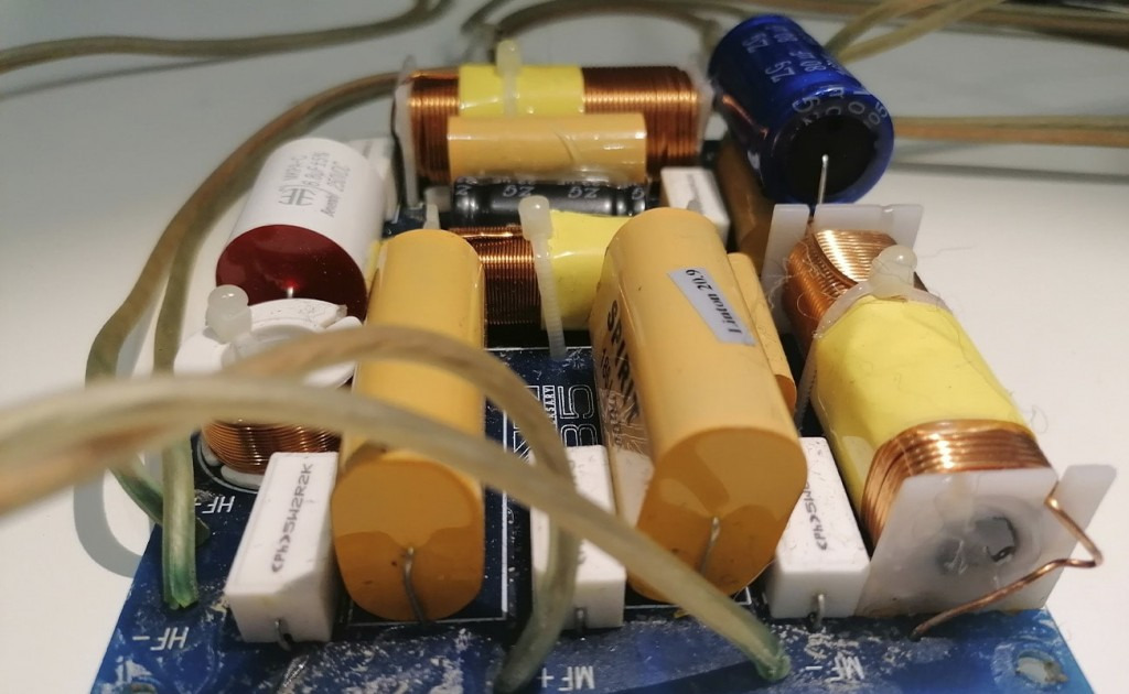
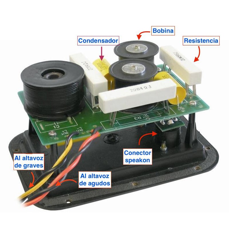
A passive filter is the most frequently used and is the simplest version. These use a combination of capacitors, inductors, and resistors to filter and divide the signal coming from the power amplifier, so it can be sent to two or more speakers (transducers). This type of filter is found in stereo speakers but is also very common in home theater speakers.
While a passive filter uses only the electricity present in the signal sent by the amplifier, an active filter uses a separate power source.
Home theater and surround sound systems use a crossover filter to separate the sub-bass frequencies and send them to the subwoofer, sending the rest of the low, mid, and high frequencies to the other speakers located around the listener. Typically, the signal received by each speaker is separated by another passive crossover filter for each speaker (transducer).
Due to this power requirement, active crossover filters are present in speakers that need a power source (powered monitors or stereo speakers). They are also applied to soundbars, home theater systems, whole-home audio systems, and Bluetooth speakers.
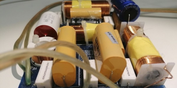
Construction of a Filter
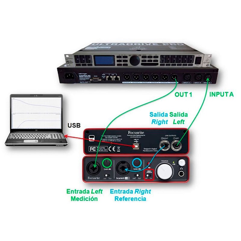
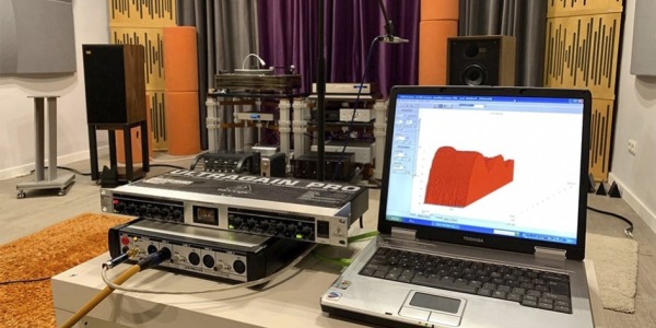
Thinking about how to make the filter is the hardest part of building a speaker. It may be that there isn't even a filter that makes two speakers work together. There are several ways to design and build a filter. Unfortunately, it's not enough to design a filter on the computer, build it, and connect it directly to the speaker. Translating theory into reality always requires some knowledge and it is almost essential to have a tool that can measure the response the filter gives when integrated into the transducer-room system.
On the other hand, there are unpredictable effects, especially the speaker's ability to reproduce part of its corresponding band without creating distortion or coloration. This can only be verified experimentally.
Regarding power constraints, if you intend to create speakers capable of generating very high sound pressure and/or will be used in a very large room, you must consider the type of tweeter used and the crossover frequency should be set at a high frequency, and the filter slope should be at least 12 dB/oct in any case. There are other derived restrictions that are not so obvious. For example, the DC resistance of a coil. Its power determines the amount of copper in its section, but this area is inversely proportional to its series resistance (Rdc), which interacts very noticeably with the filters.
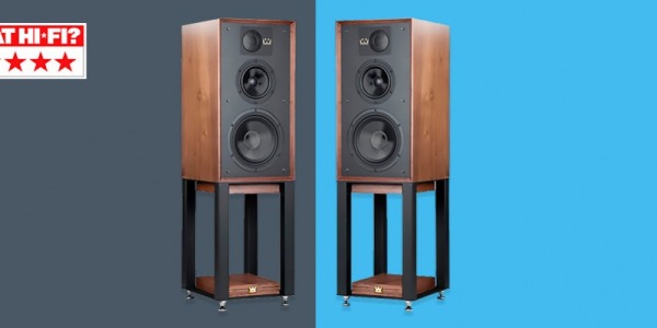
It is advisable to have the auditory reference of a good or VERY good speaker, because after hours of listening, the notion of what is right or wrong is lost.
Recommendations:
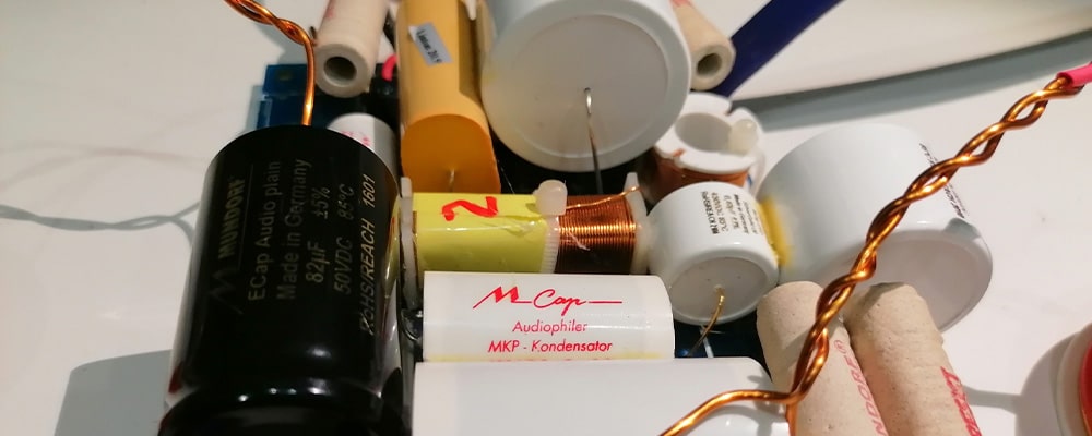
It is highly recommended to use high-quality components.
It is recommended to use metal film resistors for attenuating the tweeter.
Regarding coils, unless absolutely necessary, it is not advisable to use coils with ferrite cores, but rather air cores (ferrite behavior is not entirely linear with current and it saturates). The iron core option is more interesting. It is used for very high inductance values and does not perform well at high frequencies, but for filters at frequencies below 350Hz, it is a suitable option. An air-core coil with those values would be very large, and the quality/price ratio would not be good.
Another thing about coils. In any type of filter, no matter what, coils should NEVER be placed on the same plane; magnetic fields couple. Coils should be placed perpendicularly, at 90º angles. This significantly reduces induction between them.
It is not advisable to use cheap electrolytic capacitors, especially in the highs.
For measurements, it is useful to have something that shows the frequency response, such as a good microphone, a recording of pink noise, and a frequency analyzer for the computer.
Filters can be mounted on a PCB, although the traces are very thin and offer more resistance than cables, and they degrade and oxidize if not protected with waxes or varnishes. In the case that they oxidize, the oxide quickly degrades copper conduction because the traces are so thin.
If done on a PCB, the traces should be as large as possible to avoid abrasion of the material.
The most recommended option is wiring. It involves fixing the components on a board and soldering the terminals with wire or directly to each other.
It is also advisable to use high-quality gold connectors, as poor ones oxidize and can allow several amperes to pass through them.
If you have any questions or need personalized assistance to create your own filter, do not hesitate to contact us.

Comments (0)